Sony/NEC Projector and General Mediaroom Information
| The information presented here is garnered primarily from posts to the AVS Forum. Many thanks to the folks there for helping to assemble this information. |
Software
|
PJ Calc - A handy utility that Sony has to calculate the proper distance from the screen to the projector. |
|
Documentation
| Sony VPH 12XX | 125X / 127X FAQ - Under Development | |||||||||
| Cover, Specifications, Content - Courtesy Jerry Arseneau | ||||||||||
| Connections - Courtesy Jerry Arseneau | ||||||||||
| Adjustments - Courtesy Jerry Arseneau | ||||||||||
| Misc - Courtesy Jerry Arseneau | ||||||||||
| 5 BNC Adjustment - Used to allow saving of aspect ration information. Card in slot A can store 8, while card in slot by can store 1. | ||||||||||
| Disassembly, Service Manual Chapter 2 - Courtesy Jerry Arseneau | ||||||||||
| Setup, Service Manual Chapter 4 - Courtesy Jerry Arseneau | ||||||||||
|
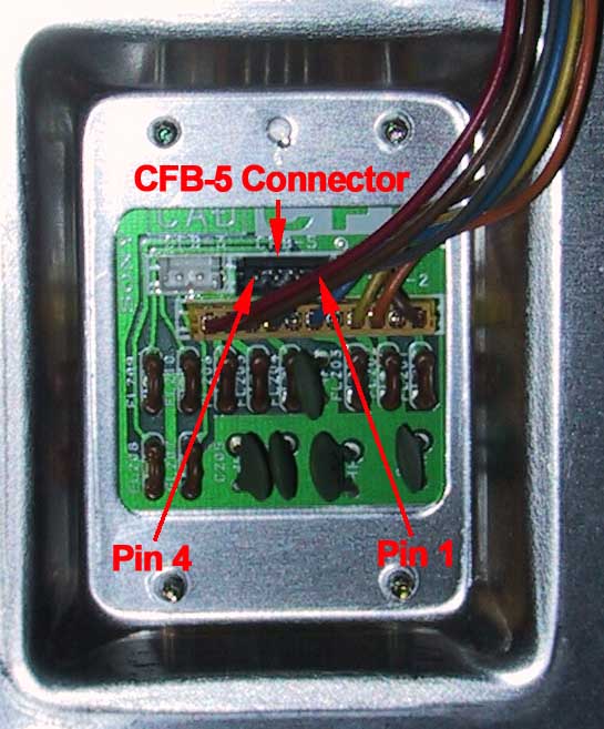
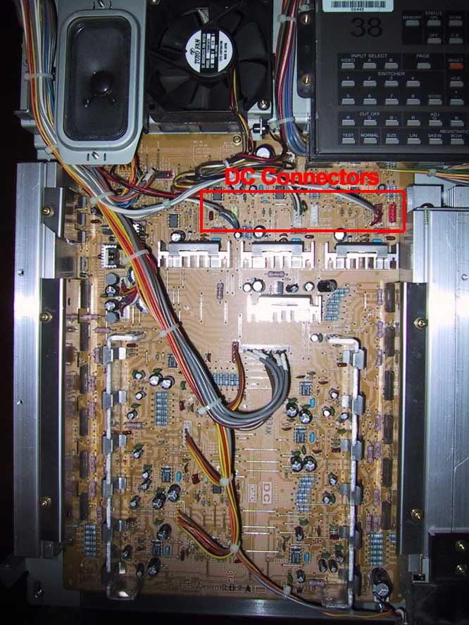
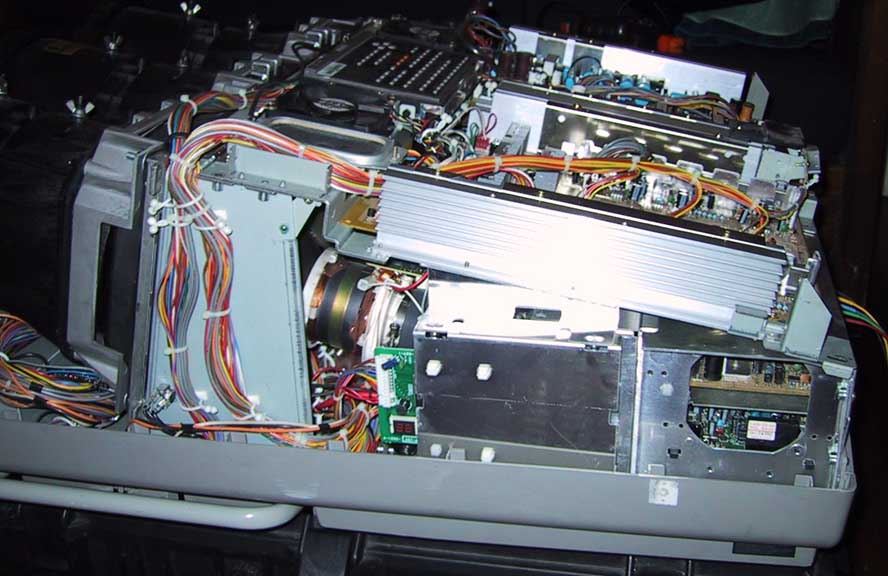
G2 Adjustment Procedures - Courtesy Chuck Williams If the AKB, or "automatic cathode balance" circuit is working, or was not disabled, those other pots (they are called "screen" or "G2" adjusts) shouldn't be super critical. For instance, if you nudge the green one up a little, you should see the projector "try" to turn it back down. Similarly if you turn it down, the projector tries to correct this. If changing them made a huge difference, it's possible that the AKB was disabled by a previous user. The reason someone might have done this is to get rid of the AKB line at the very top of the screen (usually off the screen and on the wall) which some people find annoying. Do you have a voltmeter? If so, there are voltages you can measure on the small CFB board under the fold down (fold up if it's on the floor) boards to set the G2's. Set the unit into Service mode, press the Page key and make sure the unit is set to 6500 color temp, press the Bias key, press the left and right arrow keys simnultaneously until the message "Factoryu Preset Data?" is displayed, and press the up key for yes. Then measure the voltage between chassis and pin 2 of CFB, and adjust the blue G2 for 4 volts. Do the same with green and red at pin 3 and pin 4." "The "screen" controls are the G2 controls. G2 stands for Grid #2, also known as the "Screen Grid" and has nothing to do with the screen you are projecting on. To set your 2 and 4 pole magnets, yes you must have it on and stick your hand inside. It's a little ballsy if you haven't done it before, just keep one hand in your pocket and you'll be OK. Display a dot pattern and turn up the contrast to a high level. Take, for example, the green electrical focus control and rock it back and forth. In one direction of rotation, the green dot should become uniformly fat and round, or at least symmetrical. In the other direction of rotation the dot should be observed with a halo around it. If this is not so, use the 2 pole magnet (the one closest to the CRT socket) to try to get the dot in the middle of the halo. Rotate the focus control back the other way and use the 4 pole magnet (the one closest to the convergence and deflection yokes) to make the dot uniformly fat. Youll have to go between the 2 and 4 pole alignments until its set." Images Showing Related Components |
||||||||||
|
2/4
Magnet Adjust Procedures - Courtesy Chuck Williams |
||||||||||
|
Miscellaneous
1252 Images
|
||||||||||
| Pronto CCF - compiled by aalbert | ||||||||||
| D50Q |
|
|||||||||
| D50HTU |
|
|||||||||
| G70 Series |
|
|||||||||
| G90 |
|
|||||||||
| Serial Port Specs |
|
| NEC | XG85 & XG135 - Courtesy NecTech | |||||||||||||||
|
Note - These manuals also apply to many of the Runco models, which are based on the NEC
|
Line Doublers / Image Processors
| Faroudja | 5000, 3000, 2200, NR, 401, 301 - Courtesy Faroudja | |||||||||||||||||||||
|
|
| DVDO | iScan Pro, iScan Plus v2 - Courtesy DVDO | |||||||||
|
|
Last
Modified on June 17, 2001
aalbert@biggerhammer.net