Rate of fire
. . . . . . . . . . . . . . . . About 1000 rounds per minute
..........................................................................................................Lbs.Ozs.
Flexible
gun with sights and retracting slide.................................. 22
8
Fixed or Wing gun with operating slide...........................................21
4
Weight
of
100 cartridges in links......................................................6
12
Weigh
of
barrel...................................................................................3
12
Weight of Metallic Link Filler............................................................8
~13
Length
of
barrel..............................................................................
23.9 inches
Length
of
gun (Flexible)..................................................................39.4
inches
Length of gun (Fixed).....................................................................39.4
inches
Regular equipment with each Flexible or Fixed or Wing Gun is as follows:
SPARE PARTS
1 Extractor complete consisting of:
1 Extractor
1 Extractor Plunger
1 Extractor Plunger Pin
1 Extractor Plunger Spring
1 Elector
1 Ejector Pill
1 Ejector Pin Spring
1 Ejector Spring
1 Sear complete consisting of:
1 Sear
1 Sear Spring
1 Sear Spring Plunger
1 Sear Spring Plunger Pin
1 Driving Spring
1 Firing Pin complete with Spring and Pin
1 Firing Pin Spring
1 Firing Pin Spring Pin
1
Ejector complete with Ejector Pin Spring
2 Ejector Pins
1 Sear Stop with. Pin complete
1 Cover Extractor Spring
1 Bolt Stud
(to suite type of gun)
1 Belt Holding Pawl Pin complete
1 Belt Holding Pawl Spring
1 Belt Feed Lever Spring Plunger
1 Belt Feed Lever Spring
1 Belt Feed Pawl Spring
12 Cotter Pins (assorted sizes)
ACCESSORIES
1 Oil Can (filled)
1 Combination Punch
400 Metallic Links
1 Metallic Link Filler
1 Cleaning Rod
1 Drift
1 Ruptured Cartridge Extractor
(to suit caliber)
1 Leather Case for Spare Parts and Accessories
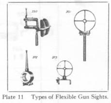
Sights are provided with each Flexible Gun.
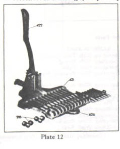
A Retracting Slide is provided with each Flexible Gun.
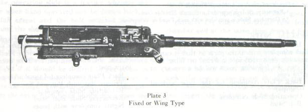
An Operating Slide is provided with each Fixed or Wing Gun.
SPECIAL
NOTE:
Back Plate complete (of the type without grips)
Operating Slide complete
Bolt Stud
Similarly, if it is desired to have Fixed or Wing type gun complete with extra parts so that it can be instantly converted into a Flexible type of gun, the following parts will be necessary at extra cost :
Back Plate complete (of the double grip type) Trigger Bar with I'M and Spring
Retracting Slide complete
Retracting Slide Bolt Stud
Sights complete with bases.

Detailed Action
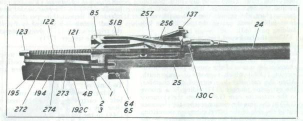 Starting with
the gun loaded, when the trigger (271)
is
pressed the front end of the trigger bar
(272) is caused to move upwards and acting upon the sear holder (245 1/2)
raises it. The
sear holder is
in
close contact with the sear (243 1/2) and a cam formed oil the sear riding
in a notch in the sear holder causes the sear to move laterally thus releasing
the firing pin (174) which flies forward under the action of the firing pin
spring
(175) and discharges the cartridge. At
I
he time of the explosion, the barrel (24) recoils to the rear carrying with
it the barrel extension (23) and the bolt (51B) which is locked to the barrel
extension by the breech lock (61). When the barrel and the barrel extension
have recoiled about
3/8
of an inch the breech lock pill (64) strikes the slanting surfaces Of the
lock frame tri projections causing the breech lock (61) to leave its recess
in bolt and slide down the breech lock
cam (62). At-full recoil of about 5/8 of an inch, complete unlocking of the
bolt takes place.
Starting with
the gun loaded, when the trigger (271)
is
pressed the front end of the trigger bar
(272) is caused to move upwards and acting upon the sear holder (245 1/2)
raises it. The
sear holder is
in
close contact with the sear (243 1/2) and a cam formed oil the sear riding
in a notch in the sear holder causes the sear to move laterally thus releasing
the firing pin (174) which flies forward under the action of the firing pin
spring
(175) and discharges the cartridge. At
I
he time of the explosion, the barrel (24) recoils to the rear carrying with
it the barrel extension (23) and the bolt (51B) which is locked to the barrel
extension by the breech lock (61). When the barrel and the barrel extension
have recoiled about
3/8
of an inch the breech lock pill (64) strikes the slanting surfaces Of the
lock frame tri projections causing the breech lock (61) to leave its recess
in bolt and slide down the breech lock
cam (62). At-full recoil of about 5/8 of an inch, complete unlocking of the
bolt takes place.
The barrel extension (25) recoiling on to the back of the accelerator (1) forces it to the rear and the claw of the accelerator engaging with the shoulder in the bottom of the bolt (51B) separates it from the barrel (24) and throws it to the rear against the action of the driving spring (121).
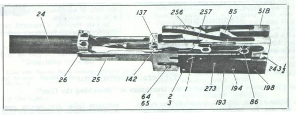 As the bolt (51B)
moves to the rear, the extractor (137) draws a cartridge from the links and
as the extractor is forced down by the cover extractor cam (101), it forces
the cartridge down into the groove oil the face of the bolt. At the same time
the ejector (130C) pushes the empty cartridge case down out of the face of
the bolt and it drops it from the gun. As the bolt (5113) moves to the rear,
the firing pin (174) is cocked by tile action of the cocking
As the bolt (51B)
moves to the rear, the extractor (137) draws a cartridge from the links and
as the extractor is forced down by the cover extractor cam (101), it forces
the cartridge down into the groove oil the face of the bolt. At the same time
the ejector (130C) pushes the empty cartridge case down out of the face of
the bolt and it drops it from the gun. As the bolt (5113) moves to the rear,
the firing pin (174) is cocked by tile action of the cocking
lever (85) riding in the top plate bracket (263) which is attached to the top plate (262). At the same time, the belt feed lever (151) riding in its cam groove in the top of the bolt, moves the belt feed pawl (161) lateral]y into position behind the next cartridge. While this action is taking place, the ammunition belt's prevented from failing back out of the gun by the belt holding pawl (43).
When the backward motion is completed, the driving spring (121) comes into play sending the bolt forward. The cartridge is held in the face of the bolt in the correct position to enter the chamber by means of the curved portion of the ejector (130C) which supports it underneath. After the cartridge has entered the chamber, the extractor plunger (142) riding in a groove in the extractor cam (138), raises the extractor (137) at the time the ejector reaches the clearance cut in the side of the barrel extension permitting it to swing out and leave the cartridge in the chamber as the extractor is raised.
As the bolt (51B) is nearing the end of its motion, it carries the barrel extension (25) forward and at the same time the breech lock (61) which moves forward with the barrel extension, is forced to ride up the breech lock cam and engage behind the shoulder n the bottom of the bolt, thereby locking the bolt to the barrel extension. If pressure is maintained upon the trigger the sear holder (245 1/2) is raised and sear disengaged as soon as the bolt has reached its forward position, thereby releasing the firing pin and causing the cycle of action above described to be repeated.
Manipulation
To
Load:
(Flexible Gun)
Without opening the cover, push the end of the loaded metallic belt through the feed opening as far as it will go, so that the first cartridge held by the belt holding pawl (43), prevents the belt from slipping back out of the gun. (Note: Insert bell so that the part of link marked "Colt" or caliber of gun is uppermost.) Pull the retracting slide handle (344) to the rear as far as possible and release it. Repeat this operation and the gun is loaded. Unless it is desired to fire immediately, the trigger safety (277) should be put on thereby locking the trigger (271).
To Fire:
Push the trigger safety (277) to left and press the trigger (271). Firing will continue as long as the trigger is pressed and there are cartridges in the belt.
To
Unload:
Unlatch and lift up the cover (91). Lift the belt of cartridges out of the
feed opening and close the cover. Pull the retracting slide handle (344) to
the rear as far as it will go ejecting the cartridge which remains in the
chamber. Point. the gun in a safe direction and snap the trigger to release
the tension on the firing pin spring and also to make sure that the gun is
unloaded.
Correction of Stoppage
If a stoppage occurs, pull the retracting slide handle to the rear as far as it will go and release it. This throws out the cartridge that was in the chamber and inserts another one. If on attempting to fire, this does not remedy the difficulty, lift up the cover and see if a battered or thick-headed cartridge is held in the face of the bolt. If so, remove it by pushing it upward with a screw-driver.
In case there is a ruptured cartridge in the chamber examine for reason and then, if necessary, re-adjust the headspace.
If the difficulty recurs and the cause is not apparent, examine the gun for broken parts.
General Instructions
Adjusting the Headspace or "Breeching the Gun":
 |
|
"Breeching
the Gun"
Note: Make sure that the barrel locking spring is in the disengaged position, described above, before attempting to unscrew the barrel. |
If, when the gun has been assembled, the position of the bolt stud indicates that the bolt does not go fully home remove the barrel with barrel extension from the gun again and after raising barrel locking spring out of notch in barrel and sliding to side unscrew the barrel in the extension one notch at a time until it is seen by trial that the bolt breeches. Replace barrel locking spring in barrel notch.
To Strip the Gun:
(Flexible and Fixed or Wing Types)
Open the cover then move latch lock (9) to right so that back plate latch (14) can be released. Slide back plate upwards and out of the gun. Press in and away from side plate on the end of the driving spring rod (122) to release driving spring rod head (123) from slot in the right side plate (253). Draw the retracting slide handle (344) in the Flexible gun or operating slide handle in the Fixed or Wing gun to the rear until the bolt stud is ]it line with the enlarged portion of slot in side plate then remove stud from bolt. Pull the bolt complete out of the rear end of the gun casing. Note: The assembled driving spring unit need not be removed from the bolt to do this. With the point of a cartridge or drift press in on the lock frame retainer (195) through the hole in the right side plate (253). Remove from the gun casing the lock frame (192C-193), together with the barrel extension (25) and barrel (24).
Grasping the barrel in the left hand and the lock frame in the right hand, press the accelerator (1) forward, thus separating the lock frame from the barrel extension. Place the barrel locking spring (26) in the disengaged position and unscrew the barrel from the barrel extension.
Remove the cover from the gun casing by removing cotter pin (98) and then the cover pin (97).
The gun has now been separated into the following groups: The gun casing; the cover, including the feed mechanism, the back plate with its assembled parts; the bolt with extractor; the lock frame with accelerator, etc.; the barrel extension; the barrel.
Note:
This is as far as the gun should be stripped
away from a base.
For further stripping, proceed as follows but this work should on1y be carried out in a workshop.
The
Gun Casing: To Strip:
Remove cotter pin (95), cover detent pawl (94) and cover detent spring (96).
Pull out the belt holding pawl pins (44) after first removing retainer pin (38). Remove belt holding pawl (43) and spring (46) also front cartridge stop (80) and rear cartridge stop (81).
Do not remove the breech lock cam (62) but, if it must be removed, in re-assembling replace cotter pin (63) in nut (66) so that the cam (62) has the same small amount of play as before:
Remove mount adapter bolt nut cotter pins (206 and 206 1/4) and unscrew nuts (205 and 205 1/4). Remove bolts (204 and 204 1/4) and mount adapter, front (210).
Remove mount adapter screws (207) and remove mount adapter, rear (203).
Note: This is as far as the gun casing should be stripped.
To assemble, reverse the above procedure.
The Cover and Feed Mechanism:
To Strip:
Remove belt feed lever pivot stud cotter pin (153) and, using the point of a cartridge, pry the belt feed lever (151) off its stud (152) taking care while doing so that the plunger (157) and belt feed lever spring (156) do not fly out.
Note: In removing the belt feed lever see that the toe of the lever is in line with the slot in the cover otherwise it will not pass out . Remove belt feed slide (17 1) complete from its guides in the cover (91). Remove plunger (157) and spring (156) from the belt feed lever (151).
To strip the belt feed slide (171 ) push out the belt feed pawl pin (164) which will enable the belt feed pawl (161) belt feed pawl spring (166) and belt feed pawl arm (162) to be separated. Do not remove the belt feed pawl arm pin (163) from the belt feed pawl (161). Push out cover latch spring stud cotter pin (115) and remove cover latch spring (113).
Remove cover extractor spring (104B).
Note: Do not strip the cover latch assembly (106, etc.).
To assemble, reverse the above procedure.
The Back Plate: (Flexible Gun) To Strip:
 Remove trigger
pin cotter pin (276) washer (50) trigger pin (275B) spring (10B) back plate
latch lock (9) trigger (271).
Remove trigger
pin cotter pin (276) washer (50) trigger pin (275B) spring (10B) back plate
latch lock (9) trigger (271).
Remove back plate latch pin (16) then remove back plate latch (14) latch spring (18) and plunger (19). Unscrew trigger safety bracket screw (279) then remove trigger safety spring (280) and trigger safety spring plunger (281). Remove trigger safety (277) and trigger safety bracket (278). Unscrew adjusting screw (6) with plunger (7) and spring (8) and remove buffer discs (70) and buffer plate (71).
To assemble, reverse the above procedure.
The adjusting screw (6) must at all times be tightly screwed down upon the buffer discs (70).
This requires attention from time to time.
The Back Plate: (Fixed and Wing Type Gun) To Strip:
Remove latch spring stop cotter pill (21) washer (50), spring (10B), stop pin (22 1/2) latch lock (9) and back plate latch spring stop (22).
Remove latch pill (16) and back plate latch (14), back plate latch spring plunger (19) and spring (18). Unscrew the adjusting screw (6) with plunger (7) and spring (8) and remove buffer discs (70), and buffer plate (71).
To assemble, reverse the above procedure.
The adjusting screw (6) must at all times be tightly screwed down upon the buffer discs (70).
This requires attention from time to time.
The Bolt: To Strip
Remove the driving spring assembly (121, etc.). Remove the extractor (137) by turning it to a vertical position and pulling it out.
Remove bolt switch (256) bolt switch plunger (257) and bolt switch plunger spring (258) from bolt.
Remove cocking lever pin (86) and cocking lever (85).
Using point of a cartridge or the cocking lever press in on the sear (243 1/2) which will cause firing pin (174) to snap forward. Using the cocking lever, swing the sear stop (247) out of its groove in bolt into center of bolt then push sear stop pin (248) from underneath with a drift and remove sear stop with pin.
Slide the sear holder (245 1/2) with its spring (249C) and plunger (250B) upwards out of the bolt. Remove sear (243 1/2) complete from bolt by sliding it laterally a short distance then lifting out.
Remove firing pin from bolt.
To assemble, reverse the operations.
Note: In assembling the sear (243 1/2) in bolt, if the bolt is to be employed in a Fixed or Wing Type gun, place the sear (243 1/2) in the bolt with the end carrying the sear spring. plunger and sear spring at the side next to the trigger-motor or solenoid.
The
Extractor:
To
Strip:
With the point of a drift, push oil the end of the ejector pill (131) and remove pin together
with ejector (130C)) ejector pin spring (132) and ejector spring (133).
Caution: -- Use care to see that lite ejector and ejector spring do not fly out -while the eiector pin is being removed.
To assemble, reverse the operations.
Note: In replacing the ejector pin (131), see that the V notch is uppermost so as to engage with the ejector pin spring (132),
The
Firing Pin: To Strip:
Using a drift, push out the firing pin spring pin (176) and remove the firing pin spring (175).
Note: Take precautions to prevent firing pin spring from flying out during tile operation.
To assemble., reverse the operations.
The Lock Frame: To Strip:
Push out accelerator pin (2-3) and remove accelerator (1).
With the aid of a drift, push out the lock frame retainer (195) and spring (196).
In the Flexible Gun push out trigger bar pin (273) arid remove trigger bar (272) and trigger bar spring (274). Remove barrel plunger (27) and barrel plunger spring (29) from the lock frame, precautions being taken to prevent the plunger and spring from flying out during the operation.
To assemble, reverse the operations.
The Barrel and Barrel Extension: To Strip:
Detach lock frame (192C-193 etc.) from the barrel extension (25). Unscrew the barrel (24) from the barrel extension after first having raised the barrel locking spring (26) out of the barrel notch and after it has been slid over into the disengaged position.
After barrel is separated from barrel extension, slide the barrel locking spring (26) out of extension. Push out the breech lock pin (64-65) and remove breech lock (61).
To assemble, reverse the operations.
Replace the breech lock (61) with bevel faces to front and double bevel on top.
Re-positioning of Parts
In order to change a gun feeding left-hand to feed right-hand or vice-versa, repositioning must be carried out in the following groups of parts:
I. The Feed Mechanism in the Cover
II. The Bolt and Extractor
III. Certain fittings in the gun casing
In order to change over a gun feeding left-hand to feed right-hand proceed as follows:
I. The Feed Mechanism in the Cover.
Open cover and proceed as indicated for stripping cover and feed mechanism. Remove the plunger (157) arid spring (156) from rear hole in the belt feed ]ever and place in front hole. With the belt feed pawl (161) stripped, as described under "The Cover and Feed Mechanism: To strip," place the belt feed pawl arm (162) in position on the pin (163) so that, in the assembled gun and with cover closed, the arm (162) will be to the rear. Then, after putting belt feed pawl spring (166) in its position, replace the feed pawl in the slide (171) and replace pin (164). Now put the belt feed slide (171) complete back into its grooves in the cover observing in doing so that it will feed "righthand." When the gap in the belt feed slide, for toe of the belt feed lever, (151) is in line with slot in the cover (91) replace the belt feed ]ever (151) using the point of a cartridge to aid in pushing the plunger (157) and spring (156) into position. Replace the belt feed ]ever pivot stud cotter pin (153). This completes the changes in the feed mechanism in the cover to afford right-hand feeding.
II. The Bolt and Extractor.
To change front left-hand to right-hand feeding.
Remove bolt complete from gun. Remove the extractor (137) and with the point of a drift push on the end of the ejector pin (131) and remove it. Note: Use care to see that ejector (130C) and ejector spring (133) do not fly out when doing this. Place ejector (130C) and spring (133) in position suitable for right-hand feeding (See Insert Diagram) arid replace the ejector pin (131) with the V notch uppermost.
To change the switch position:
With the extractor removed from the bolt, with forefinger and thumb raise the bolt switch (256) high enough to be clear of the bolt switch plunger (2,57) then give the switch a half turn when it will be seen that the other hole in the switch will come in line with the plunger (257). Push down switch and replace the extractor. This completes the changes in the bolt and extractor to afford right-hand feeding. I
III. The Fittings in the GunCasing.
Remove retainer pins (38) and withdraw the belt holding pawl pins (44) from each side which will enable the front cartridge stop (80), rear cartridge stop (81) and belt holding pawl (43) and spring (46) to be taken out and their positions reversed to suit the opposite hand feeding.
Change operating slide from one side to the other in fixed or wing type gun. Change retracting slide from one side to the other in the flexible type gun.
Replace bolt complete in gun, insert bolt stud in lefthand side of the bolt. Replace driving spring.
This completes the repositioning of parts to enable the gun to be fed from the right-hand side.
Reverse procedure to change from right-hand feed to left-hand.
To Convert a Flexible Gun into a Fixed or Wing Gun:
1. Remove retracting slide.
2. Remove sights and sight bases from the gun.
3. Remove back plate of the Flexible type.
4. Remove bolt and retracting slide bolt stud.
5. Withdraw partially, lock frame, barrel extension and barrel from gun and remove trigger bar, trigger bar pin and trigger bar spring from the lock frame.
6. Replace lock frame. barrel extension and barrel in gun.
7. Replace the bolt 'with driving spring in gun, also bolt stud.
8. Attach operating slide.
9. Insert a back plate of Fixed or Wing type.
To Convert a Fixed or Wing Gun into a Flexible Gun:
1. Remove operating slide.
2. Remove back plate of the Fixed or Wing type.
3. Remove bolt and bolt stud.
4. Withdraw partially. lock frame, barrel extension and barrel from gun and place a trigger bar, trigger bar pin and trigger bar spring in position in the lock frame.
5. Replace lock frame, barrel extension and barrel in gun.
6. Replace the bolt with driving spring in gun, also the retracting slide bolt stud.
7. Attach retracting slide.
8. Insert a back plate of the Flexible type.
9. Attach sight bases and sights complete to the gun.
Care and Upkeep
1. Make certain that gun is unloaded after firing and also before proceeding with any examination, cleaning and so forth.
2. In order that the gun may be kept in good condition it should be thoroughly cleaned and oiled after firing.
3. Remove any accumulation of residuum which may have formed during firing. In this respect give attention to the inside of the barrel bearing and plug. Scrape off residuum from muzzle face of barrel and clean around barrel where it moves in the barrel bearing. Certain powders cause a greater amount of residue to form than others. This must be removed as it builds up rapidly and interferes with the gun's correct functioning.
4. Oil working parts of gun before firing. In cleaning, the barrel should be given special attention and the bore left oiled after cleaning.
5. If gun has been taken apart, in re-assembling and in placing the bolt back in the gun, be sure that cocking lever is pressed forward in bolt and accelerator is back in the lock frame which at the same time brings the barrel back into recoiled position. The bolt cannot be placed in gun with the barrel in forward position.
6. Try gun's action by pulling back on the bolt and note that bolt returns freely under the action of the driving spring. 7. See that gun is breeched correctly.
8. See that bore is clear before commencing firing.
9. Do not fire more than 50 rounds on the ground without cooling the barrel. 'When firing from an airplane, the current of air, developed by speed of the plane, acts as a cooling agency.
10. In the event of the face of the bolt receiving damage caused by burning around the firing pin hole (this results from using faulty ammunition having punctures, leaky primers and so forth), the recoil plate (241) can be replaced but this work must be done in a workshop.
11. The barrel jacket can be tightened up on the trunnion block, should it become loose from long service. To do this, remove lock screw (317), lock washer (318) and plate (316) then turn barrel jacket up tightly against trunnion block. Replace plate, lock washer and lock screw.
12. If gun appears to be losing speed after long service, it may result from weak driving spring (121). Examine and replace, if necessary.
Bolt Group Assembly
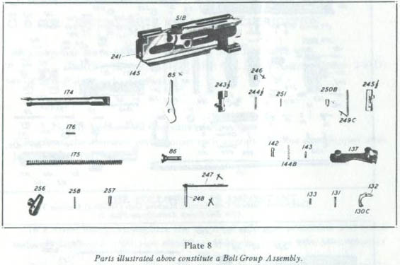
PART
NO..........NAME
OF PART