ST-HB-07-163-74
Original
THE 7.5-MM StG 57 (SIG 510) ASSAULT RIFLE
(SWITZERLAND)
162. General
a. The
7.5-mm StG 57 (Sturmgewehr 57) assault rifle is the standard Swiss Army rifle.
This weapon, developed by the Swiss SIG Company, is also known as the SIG
510 when chambered for the 7.62mm NATO cartridge. A small quantity of these
rifles also were produced by Beretta in Italy and sold in South
America. There is little military use of this rifle except by the Swiss Army;
however, the SIG 510's are offered for commercial sales in both selective-fire
and in semiautomatic fire models. The StG 57 (fig
122
and
123) is
easily identified by Its angular, ungraceful appearance; long, perforated
tubular barrel jacket; folding sights; small plastic forearm: and plastic
butt. Also, the Swiss cross is stamped over its chamber. The commercial SIG
510's
are similar to the StG 57 but can be identified by their larger wood forearm
(fig
124
and
125).


b. The
StG 57 (SIG 510) is a delay blowback-operated, detachable box magazine-fed,
selective-fire weapon, although some commercial versions are capable of semiautomatic
fire only. These rifles often are equipped with a folding metal bipod (fig
123), a foldaway winter trigger (fig 122), and a loaded-chamber indicator.

c.
The StG
57 fires 7.5x55.5-mm cartridges only; the SIG 510 series fire 7.62x51-mm cartridges
(refer to sec V).
163. Technical
Data
Technical data pertaining to the StG 57 assault rifle are presented in table
V.
164. Operation
a. Load
the magazine as described in paragraph 128a. Rotate the selector (fig 124)
to its vertical (safe) position, aligned with the letter S. Hold the magazine
so that the lips on its front edge can be mated to the recess in the receiver
(fig 127); mate the lip with recess; then pull the bottom of the magazine
rearward until the magazine catch snaps into place.
b. Move
the front and rear sights to their erect position (fig 123) if an StG 57 or
if equipped with folding sights. Adjust this model for range by rotating the
knurled drum (fig 123) until the number corresponding to the range in hundreds
of meters is aligned with the index work. If the rifle is a SIG 510 equipped
with non-folding sights (fig 124), press the lock (fig 124) and move the sight
along the base until the number on the sight base that corresponds to the
range in hundreds of meters is aligned with the sight.
c.
Grasp
the operating handle (fig 122), pull it fully rearward, and release it.
CAUTION:
The rifle is now loaded. The loaded chamber indicator protrudes above the
top front of the receiver to indicate that the rifle is loaded (fig 122 and
127). Rotate the selector forward off safe to the position for the desired
mode of fire: T for semiautomatic fire, or
A
for fully automatic fire. Aim (using a normal sight picture), and press the
trigger. The rifle will fire according to the mode of fire selected. The bolt
will remain closed between shots or bursts of fire and when the last round
in the magazine has been fired.
d. if
gloves are worn, pull the winter trigger (fig 122) down. This trigger, extending
outside the trigger guard, can be pulled by using two gloved fingers.
CAUTION:
This trigger is not guarded and can cause accidental discharges.
e. If
the rifle is equipped with a bipod, the greatest accuracy is obtained
by using it to steady the rifle while firing prone. Pull the bipod legs (fig
122 and 123) away from the barrel jacket until they lock into position. Fold
the legs by pressing them back along the jacket.
f. To
unload or clear the rifle, move the selector to its vertical (safe) position,
press the magazine catch (fig 122) toward the magazine, and rock the magazine
forward, out of the rifle. Pull the operating handle fully to the rear, hold
it, and inspect to insure that no cartridges are present. Release the operating
handle, move the selector off safe, press the trigger, move the safety back
to safe, and insert the magazine. Fold the sights and winter trigger if necessary.
165. Disassembly
and Assembly
a. Clear
the rifle (para 164f) but do not move the selector off safe or insert the
magazine. Press the butt catch (fig 123) on the stock behind the pistol grip
and twist the butt stock one-eighth turn to the left until it disengages from
the receiver. Remove the butt stock with the driving spring.
b. Pull
the operating handle rearward until the bolt can be grasped and pulled out
of the back of the receiver. The operating handle will come off the receiver
if the handle is aligned with its disassembly notches in the receiver (fig
126).
c.
Press
in on the head of the takedown pin (fig 122) and pull the pin out, to the
right. it will not come fully out of the trigger housing (fig 126). Pull the
trigger housing off the receiver.
d. Further
disassembly is neither necessary nor desirable.
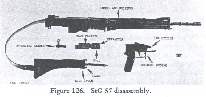
e. To
reassemble the rifle, engage the projections on the trigger housing (fig
126)
with their
seats on the sides
of
the receiver. Push the takedown pin fully home; it is necessary to press in
the head to seat the pin fully.
f. Place
the operating handle onto its rails on the receiver, with its small spring
latch forward, and slide with the handle fully forward.
g. Start
the bolt into the opening at the rear
of
the receiver. It may be necessary to move the extractor carefully to allow
the bolt to enter the receiver fully. Once in the receiver, slide the bolt
fully forward.
h. Slide
the butt stock claws (fig
126)
over the rear
of
the receiver. The stock must be twisted out
of
line with the receiver as this is done. Be sure that the point of the driving
spring seats in the recess in the bolt, then twist the butt stock onto the
receiver until the butt lock snaps into place. Clear the weapon as described
in paragraph
164f.
166. Functioning
a. The
StG 57 and SIG 510 function identically, and are both delay blowback operated.
When the trigger is pressed, the hammer is released to strike the firing pin
lever and fire the cartridge. The pressure generated during firing drives
the cartridge case rearward, and the case (part
17,
fig
127),
in turn, attempts to drive the bolt (part 4, fig
127)
rearward. The rearward movement of the bolt is, however, delayed because the
two rounded locks (part 3, fig
127)
are seated in recesses in the receiver and held there by the cam nose of the
bolt carrier (part 9, fig
127).
The rearward thrust of the bolt causes the locks to attempt to cam out of
their recesses and as they do, their pressure against the cam nose of the
bolt carrier forces the heavy carrier rearward. The delay caused by the locks
coming out of their seats and forcing the heavy carrier rearward allows sufficient
time for the bullet to leave the barrel for the gas pressure to fall to a
safe level.

b. The
bolt carrier, however, has been given sufficient momentum to travel fully
to the rear. As it does, it compresses the driving spring and rocks the hammer
rearward. The extractor (part 5, fig
127
and
128)
pulls the fired cartridge case out of the chamber and holds it to the bolt
face. As the bolt nears the end of its travel, the ejector strikes a cam surface
in the receiver (fig
129)
and suddenly pivots on its pin. This throws the fired case out through the
ejection port (fig
129).
c.
The bolt strikes the forward end of the butt stock and stops; the compressed
driving spring then drives the bolt forward. The feed rib drives the top cartridge
out of the magazine and into the barrel. As the bolt nears the end
of its forward travel, the carrier cam nose forces the locks out into their
recesses, and the extractor engages the rim of the cartridge. The bolt strikes
the barrel, the carrier strikes the bolt, and forward movement ceases.

d. The
hammer (part 14, fig 127, 129, and
130)
when released is driven by its spring (fig
130)
and strikes the end of the firing pin lever (part 11, fig 122 and
130).
This lever pivots on its pin and drives the firing pin (part 12, fig 127)
forward to strike the cartridge primer.
e. When
the selector is set at T for semiautomatic fire, it does not affect the components
of the trigger mechanism. The trigger and the sear pivot on the same pin (fig
130). As
the trigger is pressed, the connector (fig
131)
moves upward and contacts the rear underside of the sear (fig
131).
Continued trigger pressure causes the sear to pivot on the pin and release
the hammer. The hammer swings forward and strikes the firing pin lever. The
connector is a fairly heavy part, with most of its weight above its pivot.
The normal recoil of the rifle upon firing gives sufficient momentum to the
connector for it to move rearward against its weak
spring, out from under the sear. When
this occurs, the sear spring (fig 130) forces the sear back to its normal
position where
it
can reengage the hammer, upon counterrecoll of the bolt. Thus, only one round
is fired. To fire a second round, the trigger must be released; this lowers
the connector so that it can spring under the rear of the sear. Trigger pressure
will then start another cycle.


f. When
the selector is moved to A for automatic fire, the trip link (fig 13 1), because
of its joint, moves forward. This action causes the trip link stud (fig 130)
to move along the top of the sear until it fits between the sear and the disconnector
(fig 131). As the trigger is pressed the basic action in paragraph c above
takes place to release the hammer; however, the position taken by the trip
link stud now forces the disconnector to protrude into a slot in the bolt.
This slot has a closed rear end and when the bolt counterrecoils, it strikes
the disconnector and rocks it forward. The
forward movement is transmitted through the trip link stud to the sear (fig
131) and causes the sear to depress and release the hammer. This action continues
as long as the trigger is pressed and cartridges are in the magazine. When
the trigger is released, the disconnector is lowered; this breaks the connection
between the bolt and sear and firing stop.
g. When
the selector is rotated to the safe position, a projection on the selector
shaft fits into the trigger, stops trigger movement, and thus prevents firing.
h. The
loaded chamber indicator is a small spring-loaded plunger that fits into the
top rear end of the barrel. Normally the indicator is flush with the top of
the receiver, but when the cartridge is chambered, the rear of the cartridge
forces the indicator up, above the top surface of the receiver. The projecting
indicator thus signifies that there is a cartridge in the chamber.
i. There
is no last-round catch on the rifle.
167.
Accessories
a. There
are numerous accessories for the StG 57 and SIG 510 rifles, with some common
to both rifles. Accessories include:
(3) Cleaning
kit (carried in pistol grip).
(5) Grenade
sight (SIG 510).
b. The
telescopic sight is attached by fitting it onto the pads on the receiver and
rotating the lock levers on the scope base.
c.
The bayonet
is affixed by placing its ring over the muzzle while fitting the butt onto
the bayonet stud until the bayonet locks in place. Remove the bayonet by pressing
the large round catch on the butt and pull it forward off the rifle.
d. The
cleaning kit consists of a weight and string pull-through with a bristle brush
and a small clip to keep the chamber indicator out of the chamber. To use
the clip, reach into the chamber and press the indicator; when it protrudes,
slip the clip onto the groove in the indicator. The cleaning kit and night
sights are carried in the pistol grip. To obtain them, insert the point of
a bullet into the hole in the plate over the bottom of the pistol grip to
slide the plate open.
e. The
StG
57
and
SIG 510
rifles can be used to launch 22-mm inside-diameter tube grenades. Only special
blank grenade-launching cartridges can be used. The use of a bulleted round
will cause the grenade to explode while still in place on the rifle!
f. A
special grenade sight is available for the
SIG 510
to be clamped onto the barrel jacket. For direct fire, use the sight in the
manner described in paragraph
158f.
For indirect fire set the angle for the range desired, and level the bubble.
The StG
57
uses its normal front sight for direct fire, but only the
Swiss UG 58
or HPzG
58
rifle grenades can be fired because the front sight is used, in conjunction
with the ogive of the grenade, for aiming. The bipod
of the StG 58 is graduated for indirect fire. The bipod is opened, the rifle
turned sideways and a weighed string attached to the bayonet lug. The string,
when aligned with a mark on the bipod leg, sets the rifle at the correct angle
for range.
Last
Modified on April 24, 1999
aalbert@biggerhammer.net